After finishing my low power DC Tesla Coil project , I wanted to branch out into a low-mid-power SSTC, and a mid-to-high power standard typology SGTC. For the latter (Link) I am using a pretty standard design, and will probably work significantly from one or more reference designs/guides.
But for the former I will probably try to build a DRSSTC Tesla Coil with C Class driver. There are a number of reason for this, but one main one is that I recently finished a wireless power design using a pulsed C Class Amplifier design. My hope is that the two projects will end up being mutually reinforcing, as they will probably both end up operating with similar drivers and at similar frequencies.
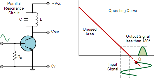
Specifically, my current C Class Amplifier design is pulsed, which will probably be useful at least for the initial testing stages of DRSSTC design. As I get further into the project, however, I hope to build a Class C driver which is self-tuning to match with the primary’s resonance frequency. (or secondary resonance frequency) The problem is that most feedback schemes won’t work for Class C drivers designs, because Class C drivers should only be turned on during some percentage of the peak positive cycle (or negative) .
http://www.electronics-tutorials.ws/amplifier/amplifier-classes.html
Most feedback schemes don’t seem to take into consideration where in the positive cycle the primary or secondary is at; only that it is in the positive cycle*.
(*or negative potentially, depending on how you have it set up.)
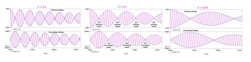
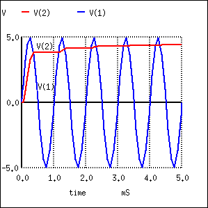
Although you could build a feedback system that only triggers the driver at a certain voltage level, this will not work straightforwardly because of the waveform pattern the primary and secondary take on due to the mutual coupling. This oscillation varies depending on the k of the coupling, and can be longer or shorter. So the feedback needs to take into account the relative level of the current cycles.
Big thanks to Christopher Gerekos because I realized the feedback was going to be an issue when I was reading this section Tesla Coil coupling from his blog.
http://hazardousphysics.christophergerekos.eu/main/zeus/The_Zeus_Tesla_Coil_2.html#theory-coupling
Via: http://www.richieburnett.co.uk/operatn2.html#coupling
For the above reasons a good feedback scheme for either project might be somewhat complicated, so I hope to kill the two proverbial birds with one stone on this project.

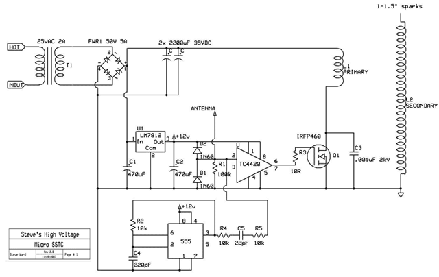
Good example of a SSTC with feedback (which I don’t think will work) from Gao Guangyan @ Loneoceans Laboratories
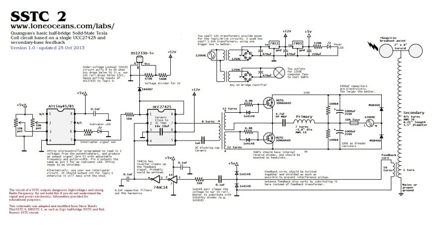
http://www.loneoceans.com/labs/sstc2/
Currently I am just at the planning stage for this. Checking out blogs on SSTC and DRSSTC designs and working on acquiring parts. (11/29/2017)
Hmm… https://www.stevehv.4hv.org/classEsstc.htm has an example of this is a Class E with feedback, so perhaps this design can work even with the mutual coupling waveform. Will investigate further. (11/30/2017)
I am kind of wondering if l could just implement a peak detector/envelope detector with a large value drain resistor set up so it quickly adjusts to the sinusoidal peak values caused by the mutual inductance, and then use a comparator or differential amplifier to compare this with the positive peak of the current* wave. This might allow me to only trigger C Class driver at the top of the positive cycle.
https://www.allaboutcircuits.com/textbook/semiconductors/chpt-3/peak-detector/
The peak detector floats just a little bit below the true peak value because of the diode’s voltage drop, for this application this is not only ok, but even ideal as the we want the comparator to output only near the peak of a positive cycle being compared with the envelope detector output. (11/30/2017)
