——— Steam Locomotive Simulation and Control System. ———
I did this project in middle of my undergraduate classes at Texas Tech University. My team was tasked with controlling a HO model train via encoded signals from the track, in compliance with NMRA standards. The train would be controlled through a LabVIEW simulation of a Steam locomotive; and LabVIEW would receive external inputs.
The technical project description is as follows:
- System simulates a steam locomotive in LabVIEW and sends outputs instructions to a rail control system over USB via UART data protocol. These signals are then interpreted by an MSP430G2553 microcontroller into power signals following NMRA (National Model Railroad Association ) standards, and send to power the track.
- The LabVIEW simulation also receives inputs from control panel over USB via UART protocol from a MSP430 chip which receives various analog and digital inputs.
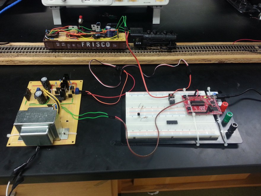
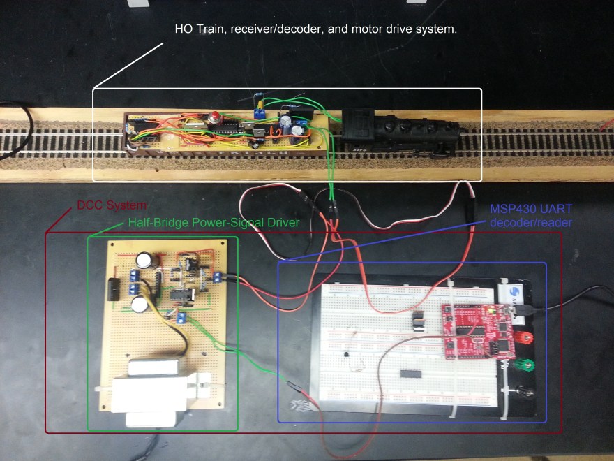
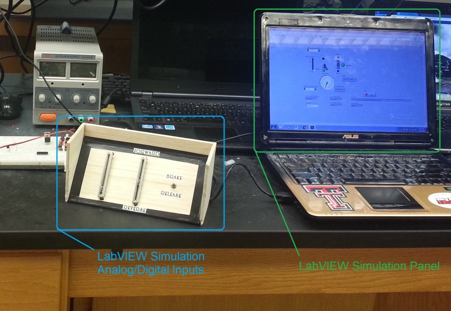
Set up with the train and controller systems being tested:
LabVIEW Simulation input set up:
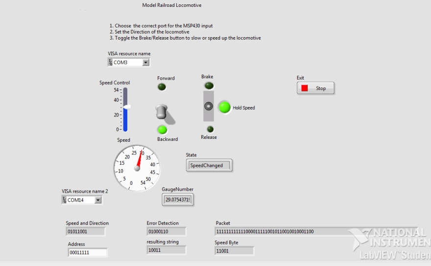
This is a screenshot of the software side of the project. LabVIEW interface panel for the Steam locomotive simulation:
Video of the train being controlled, via analog input, through the LabVIEW simulation:
The model train runs from power off the tracks. The track’s power comes in the form of modified alternating polarity square or rectangle waves, encoded with control and address information*. (*train address information) This system allows multiple trains to be controlled from the same track. Picture of the Power-Signal waveform from the rail’s control system, being read by an oscilloscope:
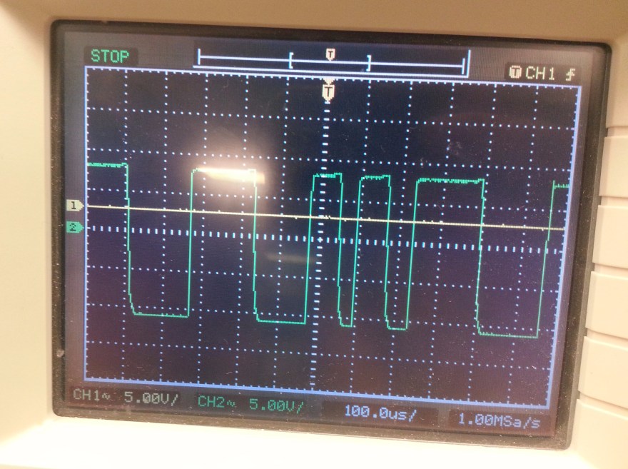
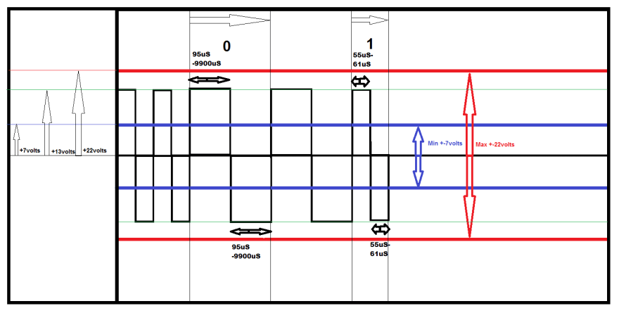
The controller had to be designed with Power-Signals in compliance with NMRA DCC signal standards. As you can see in the above the picture the ‘1’ signals are a little bit uneven, but the negative + positives cycles fit mostly within the (2x61uS = 122us) constraints. NMRA DCC signal standards:
In this video you can see the control & power signal (Bottom) from the track , and the PWM signal (Top)for the motor. This shows their effects on the train’s speed & direction.
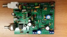
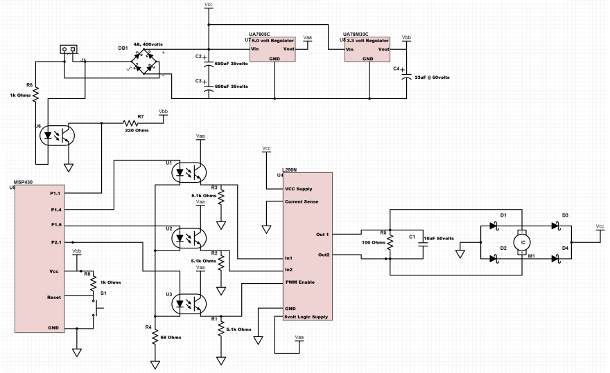
This is a schematic of the hardware on-board the actual train itself. It includes power conversion and regulation, a Power-Signal reader and decoder, and lastly a controller and isolated H-bridge driver circuit for the motor:
Going to the track is the controller circuit. The controller circuit receives an input from the MSP430 , which decodes outputs from the LabVIEW simulation via UART over USB. Input from the MSP430 are then send through opto-isolators to the half-bridge MOSFET driver, which sends the power-signals to the track. Schematic of the controller circuit setup:
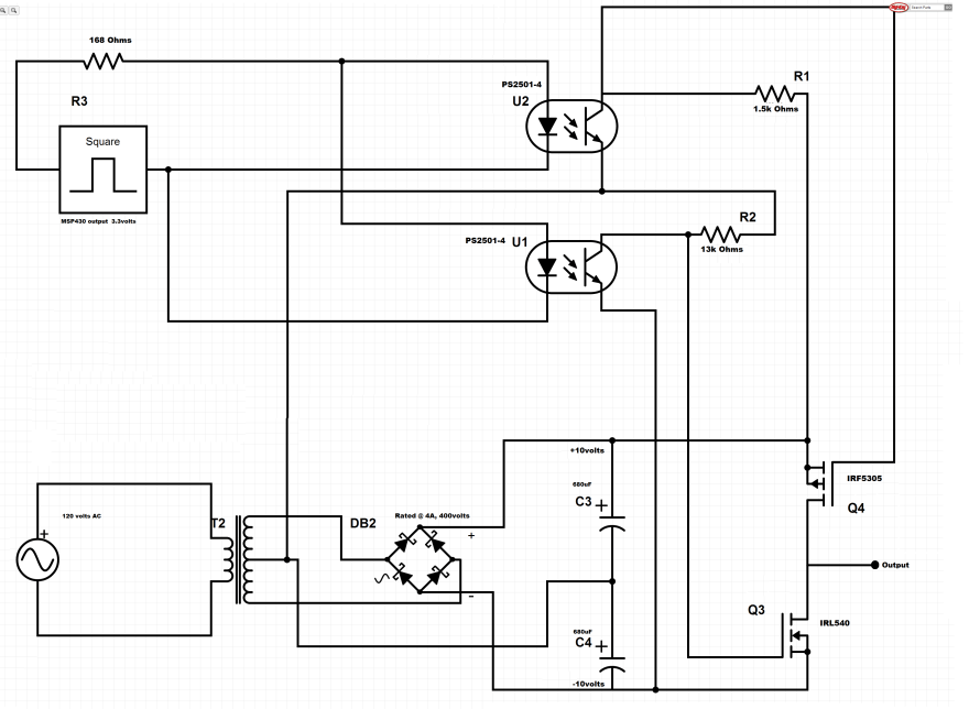
Diagram of the track set up. Half-Bridge driver powers one side of the track, and the other side is connected to the neutral:

Video of us troubleshooting the train on the tracks. We had some bugs, (Train fails to respond to reverse input) but managed to get it running by the project demo day.
On the track, and ready to roll out…