———-Sound Analyst Targeting System————
At Texas Tech my first electrical engineering project lab was to use an FPGA programmed in Verilog to control a track mounted robotic system for locating audible targets, in the 1-2.5 kHz range, and then targeting them with mechanical projectiles. My team used multiple sensors including a microphone, an ultrasonic sensor, and infrared sensors to create a system capable of identifying and locating specific audible frequencies and targeting them. A brief technical objective for the project is below:
- Autonomous FPGA controlled track driven vehicle, designed to locate and target either a 1 kHz or a 2.5 kHz sound beacon and deploy multiple projectiles to hit the target sound source.
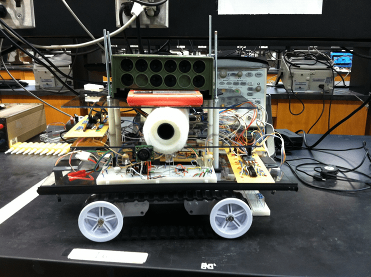
The SATS (Sound Analyst Targeting System) on a mostly empty chassis:
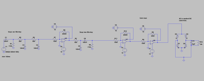
For analyzing audible signals we implemented filters for signals from the microphone. We used a double band-pass filter designed to pass 1 kHz to 2.5 kHz. The signal from the band pass filter is then put into an envelope detector, which is then read into an Analog-to-digital converter.
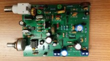
Pictured below is the filter design with the envelope detector attached at the end:
This is a screenshot of the attenuation of the microphone input through the filter modeled in LTspice. It is graphed across different frequencies:
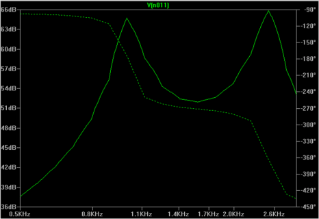
The main disadvantage of having a wide band-pass filter that includes frequencies from 1kHz and 2.5kHz is that it produces a longer roll off curve, when compared with other methods. When the filter was tested we also found to be somewhat responsive to the human voice which could cause problems. For these reasons the SATS was modified to include two separate, narrow band pass filters, at 1kHz & 2.5kHz.
LTspice model of the new narrow band-pass filters:
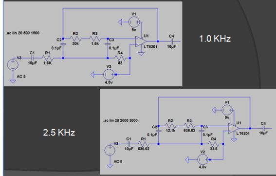
Testing the attenuation of audible signals in the 2.5 kHz range through the new band-pass filter.
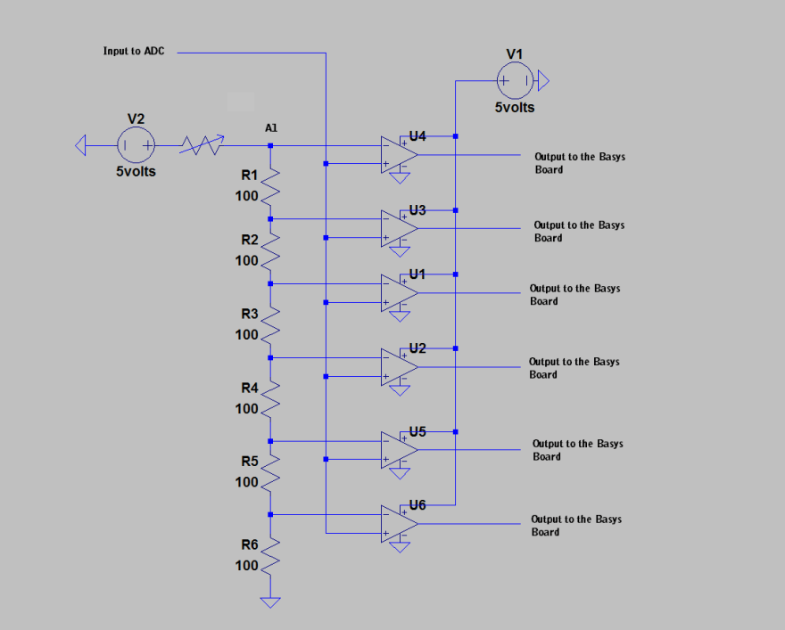
We designed a simple Analog-to-digital converter used for interpreting the output from the envelope detector into discreet logic for the Basys FPGA Board.
Design Theory, and some issues:
The SATS vehicle tracked the location of sound levels, of specific frequencies, via the vehicle location and a fixed mic input. The vehicle would drive back and forth and record audio levels. The point of highest audio levels was considered to be a target. After scanning, the vehicle would return to the position of highest audio input and fire a projectile. Although this set up worked very well for identifying the general location of a sound source, it had some difficultly with identifying the exact location and sometimes fired off the target by an inch or so.
This is a simple diagram explaining a likely cause of these difficulties in identifying the exactly location of the sound-source:
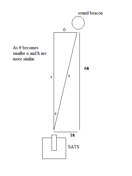
As illustrated above, the SATS vehicle was able to distinguish between locations far from the sound beacon because the distance ‘h’ varies significantly; and with the distance, also the sound intensity. However as Theta –> 0; ‘h’ –> ‘a’. When ‘h’–>’a’ sound levels become too similar and other noises become more influential on the values. In order to fix this problem a ultrasonic sensor was used to identify physical objects, and only fire at the high sound values which also had low ultrasonic sensor values. This worked very well!!
Video of an early prototype of the SATS vehicle shooting at the 1kHz or 2.5kHz sound source from a phone. (no audio)
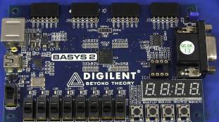
We used a Digilent Basys FPGA Board to control the SATS system and vehicle. Pictured below:
The project was designed to be run on a dark surface bounded with white lines. In this video we are testing the IR sensor functionality and reliability for the track platform.
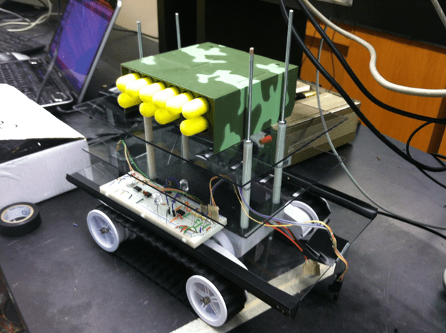
Picture of the completed project! ( -minus foam projectiles)